
Base
| Full Name | Marc Verreault |
| Organization | Optiwave Systems |
| Job Title | VP Engineering |
| Country |
Forum Replies Created
Good day,
We have examples of several OFDM systems under Advanced modulation systems/OFDM systems. The coherent examples are the best ones. I recommend taking one of these and converting to a direct detection. The Help section of the OFDM Demodulation component is very good too. It provides information on how to setup the parameters. Cheers.
Goody day,
I recommend that you place a “Convert to Sampled Signals” component before the visualizers. It will take noise bins and convert them to equivalent sampled signals. Cheers
Good day,
Please see OptiSystem User Reference Guide (Nested parameter sweeps, pp 175-180). Cheers!
Good day,
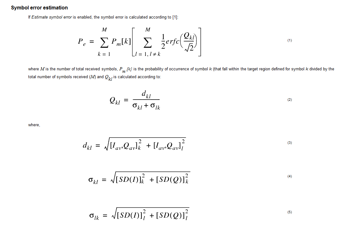
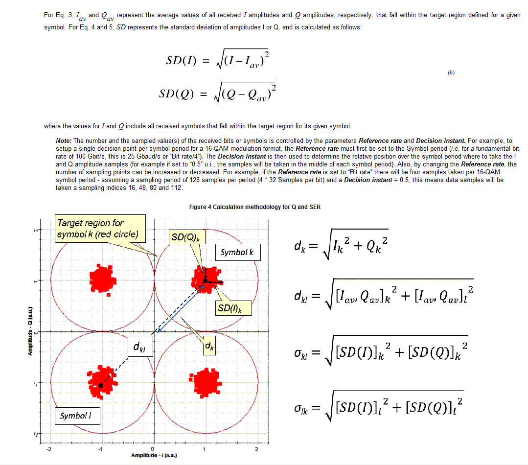
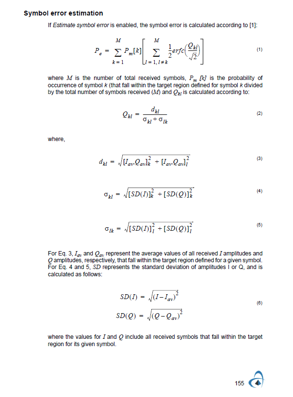
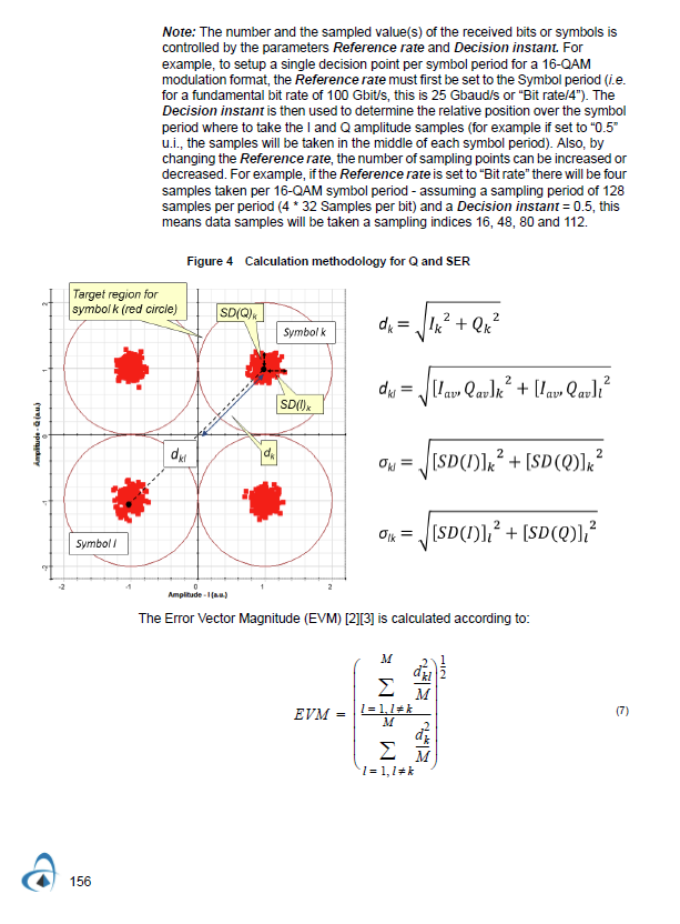
The help for the constellation visualizer explains how the Q factor is calculated. We updated the documentation for this component for OS14.1 or 14.2. Please see some clips below. Cheers. Marc
Attachments:
Good day,
The ddmz is a more physically representative model for MZ modulators (they are frequently driven from two ports to keep the voltage swing lower). The mzm modulator is just a simpler model for a MZ modulator (there are fewer knobs to tweak)
I frequently use the ddmz as it is easier to match to manufacturer specs and it can be fine tuned for different operating modes.
Cheers
Good day,
Please see Lesson 5 of OptiSystem Tutorials Vol 1. When you run multiple iterations (for bidirectional) you will need to change the index of the visualizer to see actual signals (the index selector is located on the upper right hand corner of the visualizer). Cheers.
Good day,
There is no actual time associated with the component “Optical Delay”. It is designed solely to produce a NULL signal at its output even when there is no signal at its input. Once a signal shows up at its input (after a few iterations) then the input will be carried through directly (no NULL signal will be produced).
If you want to create an actual time delay, the “Time Delay” component should be used (for Optical).
Cheers
Good day,
Yes as a minimum you need one component or a direct connection between two ports (subsystems need at least one input port and one output port to work in a simulation). Cheers.
Hi Muhammad,
Interesting project. For the VDL I believe you can use our “Time delay” component under Passives/Optical.
For the dispersion element your best bet is to use our single mode optical fiber. Cheers!
Hi Muhammad,
I recommend downloading the example “Reconfigurable All-Optical Multi-Logic Gate Based on XPM in HNLF” from our web site:
Cheers!
Hi Ehab,
Most of our components are actually pulse code modulators. For example our NRZ pulse generator works by sampling an input binary sequence to create a digitized analog representation of the rectangular waveform. We also have a measured pulse sequence generator where you can define the output signal based on a defined input amplitude-time waveform. For encryption however you may need to use our MATLAB component to process (encrypt) the sampled (digitized) signals at the transmitter and receiver. I hope this helps. Cheers.
Good day,
You have to access the contents of the data structure. For example plot(OutputPort1.Sampled.Signal) or plot(OutputPort1.Sampled.Time). It’s normally easier to declare local arrays in the MATLAB work space though. Cheers.
Hi Ankita,
Usually between 10-25 dBm. Cheers.