Optiwave software can be used in different industries and applications, including Fiber Optic Communication, Sensing, Pharma/Bio, Military & Satcom, Test & Measurement, Fundamental Research, Solar Panels, Components / Devices, etc..
OptiSystem is a comprehensive software design suite that enables users to plan, test, and simulate optical links in the transmission layer of modern optical networks.
OptiSPICE is the first circuit design software for analysis of integrated circuits including interactions of optical and electronic components. It allows for the design and simulation of opto-electronic circuits at the transistor level, from laser drivers to transimpedance amplifiers, optical interconnects and electronic equalizers.
OptiFDTD is a powerful, highly integrated, and user friendly CAD environment that enables the design and simulation of advanced passive and non-linear photonic components.
OptiBPM is a comprehensive CAD environment used for the design of complex optical waveguides. Perform guiding, coupling, switching, splitting, multiplexing, and demultiplexing of optical signals in photonic devices.
OptiFiber The optimal design of a given optical communication system depends directly on the choice of fiber parameters. OptiFiber uses numerical mode solvers and other models specialized to fibers for calculating dispersion, losses, birefringence, and PMD.
Emerging as a de facto standard over the last decade, OptiGrating has delivered powerful and user friendly design software for modeling integrated and fiber optic devices that incorporate optical gratings.
OptiConverge is a collaborative integration framework that seamlessly combines two or more Optiwave products (e.g., OptiSystem, OptiSPICE, OptiFDTD, etc.) and other third party products into unified solutions. Designed to streamline complex workflows, it empowers users to achieve their goals faster by harnessing the collective power of our trusted Optiwave tools.
attached here a file comparing the performance of DSP and DCF, the difference in the performance can be seen from the constellation visualizer.
i don’t know where is the problem, the frequency domain filter just multiply the signal by the conjugate of {exp(j*[(beta2*omega^2/2)+(beta3*omega^3/6)]), beta2,3: second and third order dispersion, omega: angular frequency} to compensate dispersion.
I attached these files, that load In-phase and q-phase components from Matlab to optisystem also the binary data, QPSK symbols for calculating BER if needed and you may need (Inphase_comp_tx_for_Q-factor)that contains In-phase component with no biasing or amplification (i.e. constellation points at [-1+1j 1+1j -1-1j 1-1j]). you could use these files and change the paths or use your own QPSK TX and RX but you will need the last two matlab component(specially matlab component 2) to compensate the dispersion.
I agree with you that the problem in the noise of the system, as when i test LMS algorithm by just adding noise to the modulated signal (without optical fiber channel), it couldn’t compensate its effect, does this problem usually occur with LMS algorithm?
I found this problem when i import my index profile either in .txt or .dat , it give me error in loading file , file is corrupted : here is the error and profile
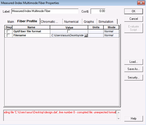
i see that but these parameters control the dispersion in optical fiber , i asked about the linear refractive index of the fiber can be changed in this component or not !!!
but this matlab component followed by another components in the system and i want to calculate BER at each time of running (i.e i want to take a vector containing all BER calculated for each run )
here is my project and the m-file called in the project but it will take long time to run also if i try another project and put the sequence length as i mentioned i get the same error
yes i use sequence length =1048576 bits as my system has a small BER around 10^-5 so i need to test the system with million bits , is there another method to test huge number of bits in optisystem