
Base
| Full Name | Junhau Khoo |
| Organization | UniMAP |
| Job Title | STUDENT |
| Country |
Forum Replies Created
Ok. I try. Thanks you for help^^
Is it the parameter same as spontaneous emission factor?
Because spontaneous emission parameter from journal is in unit of per meter, but the spontaneous emission factor in the laser like rate equation laser is no unit. This makes me confuse about them
Thank you very much^^
May I ask the brillouin scattering again?
I try the way that sir said. But the graph plotted is without any intersection between the output and backscattered power. Instead without uncheck, there got the intersection point, but the the trend for the output power is not becoming constant at SBS limit. And I try to change some parameters and refering to the article that Sir given and still cannot solve it. Is it my design or any setting is wrong?
Attachments:
Thank you^^
May I ask?
For the billouin scattering, i try to uncheck the others but the graph plotted is without any intersection. Instead without uncheck, the output transmitted power is not becoming constant at the SBS limit. Is it my design or setting got something wrong?
Attachments:
Ok, I try~thank you very much~
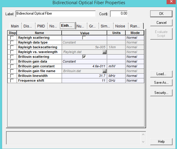
So is it means that I just check the Brillouin scattering in Enhancement and all check boxes for others like dispersion uncheck? Does this means?
Attachments:
For the Brillouin one~
Hi
Ohh…ok. I know what I should do. Thanks you very much.
Sir, I cannot open the simulation file even I use OptiSystem 15 already. That said about the violation.
This is the file
Attachments:
Ok. Thank you very much for helping.
And I have a one question. May I ask you?
Because now I use the design of Raman scattering separated channels inside the optiststem library. During the analysis, I added the Ideal Demultiplexer but the signal shown on the analyzer and meter for each channel is same. The signal shown is the output of the first channel in the input which is used as the pump signal.
What is the problem? Is it my setting wrong at the Demux part?
Why I cannot open the file? Is it because I uses the old version of optisystem which is Optisystem 7?