
Base
| Full Name | Juliana Carvalho |
| Organization | PUC-Rio |
| Job Title | Researcher |
| Country |
Forum Replies Created
Dear Damian,
About the template for a D-Shaped Fiber, I didn’t understand why do you use the channel “AirFill”?
Others doubts about Optimode:
– A fiber SMF-28 presents attenuation equal 0.2 dB/km> But, when I simulate it, in the results (Modal index, attenuation) I didn’t see any attenuation (zero). Why?
– In Default waveguide (layout window), what have to be the inserted parameter correspondent?
Thanks again!
I am waiting a help.
Regards,
Juliana.
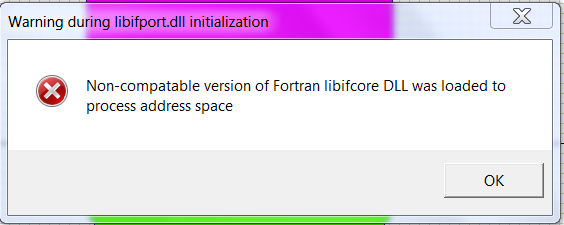
The warning.
Attachments:
Dear Damian,
Thanks for your informations!
I didn’t understand very well the meaning of calculate the loss through the effective index… Anyway, I have other doubts:
-Before the simulation, I have a warning, like is attached. But, after that is possible to see the result. But, I don’t know if is it bad or not.
-In this case of design (d-shaped fiber), the analyzes have to be anisotropic?
Best regards,
Juliana.
Hi Damian,
I tried to develope the same project and fortunately I get the software idea. So, I have now other doubts:
Is it possible evaluate the power signal propagation (in any lenght, like 1m, for example) in Optimode design?
In design profile, in channel option have an option to insert “width” value (fx). But, when I changes this value, I didn’t saw any modification in the design. What is the meaning of this parameter?
I have a lot of others doubts, but, in this moment, please, I need to know these to continuos with my work.
Thanks again!
Regards,
Juliana
Dear Damian,
Thank you very much!!! But, I can’t open the file because I don’t have the new software version. Please, could you send me with the 11 version?
Thanks again!!!
Best regards,
Juliana.
Dear Damian,
It is attached a figure that is an example about what I want to do.
Thanks very much!
Juliana
Attachments:
Dear,
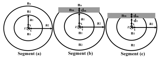
Do you have any example about D-Shaped fiber design, that I could see? I don’t know how to design this because the layers are concentrics.
Thanks again.
Best regards,
Juliana.
I am waiting any help, please… Thanks!
Dear Damian,
I am understanding my problems.
I need simulate optical fiber with extinction coefficients (imaginary factor in the cladding refractive index) and different cores. I am using 10^-6 to 0. But, I don’t know the software precision. How can I send you the project/
Thank you the attention!
Best regards,
Juliana.
Thanks for the informations! I am starting to use the software, I have a lot of doubts and few time to finish the simulations. Do you have any example about it? If yes, could you send me?
Today I installed the FDTD and BPM. I am trying to use them.
Thanks again!
Dear,
I tried to do now a drawing about my work. I so sorry if it was not good, but I can try to explain better. It is attached.
Thanks!
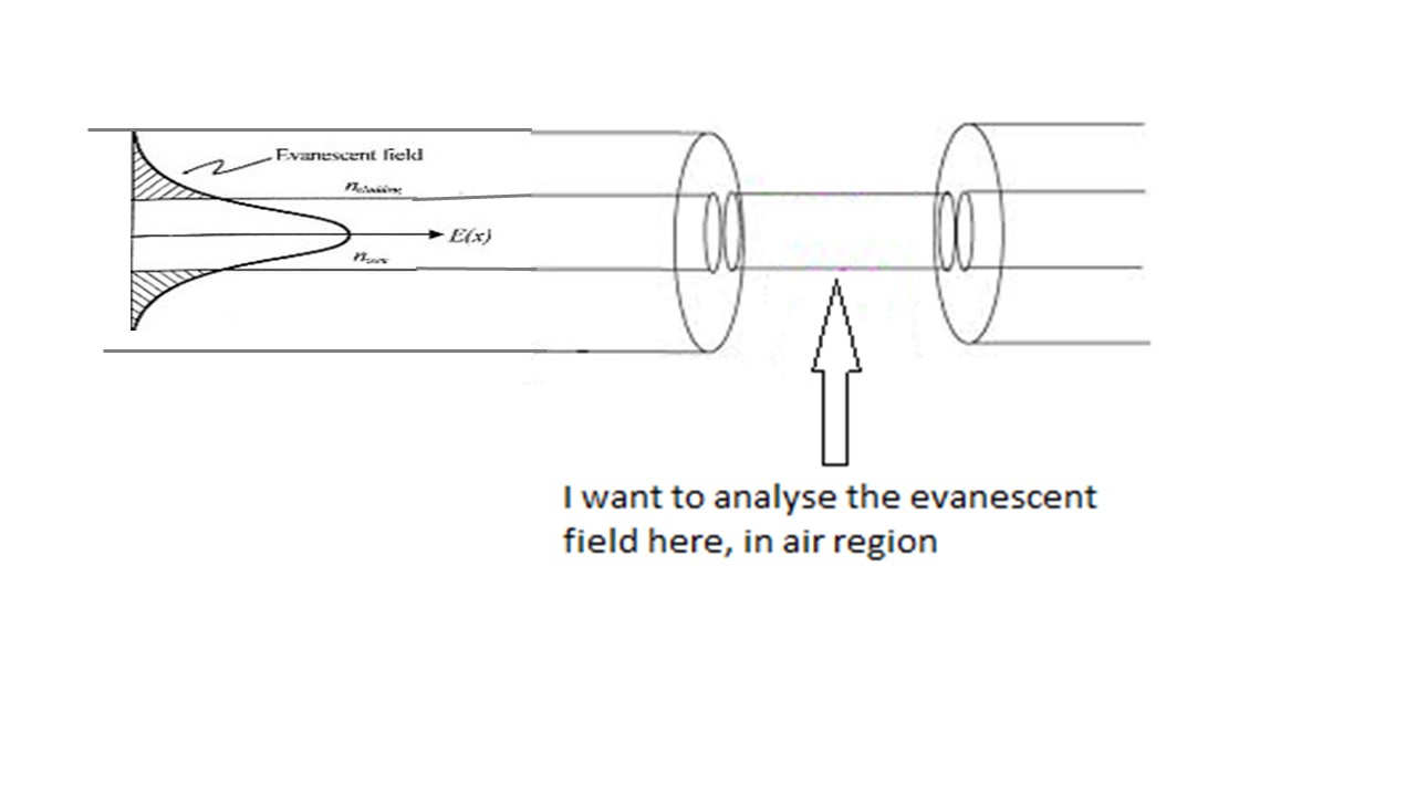

Mr. Steve,
Our first idea is to simulate a optical fiber with transmition by evanescent field. I want to do the core with refractive index of 1.452, for example, and the cladding as air (n = 1). I want to evaluate and compare with a fiber the wave propagation in both case.