
Base
| Full Name | Irfan Morshed |
| Organization | University |
| Job Title | Student |
| Country |
Forum Replies Created
As mentioned by Mr. Damian earlier, since I am upconverting 2.5 GHz signal to 60 gigs, he said I would need 8192 samples per bit. So I have made the changes and improved signal filtering, and added all your suggested corrections.
This time, the project is taking hours to calculate. I cancelled calculation after it exceeded over 2 hours!
Osd file attached.
May I kindly know what is the issue with this one?
Please help out guys! Submission is next week only .. 
Attachments:
Suggestions by others are also most welcome and eagerly anticipated! 
Mr. Damian,
As you have previously mentioned, since I am upconverting 2.5 GHz signal to 60 gigs, you said I would need 8192 samples per bit. I made the changes and improved signal filtering, and added all your suggested corrections.
This time, the project is taking hours to calculate. I cancelled calculation after it exceeded over 2 hours!
Osd file attached.
May I kindly know what is the issue with this one?
Attachments:
Dhiman,
Brother could u please correct the error and send the corrected osd file to me? I do not know how to fix it!
Please.
Bro,
I cannot access it because it does not open from optisystems version 14! That is why I requested you to kindly change the FBG wavelength and make it same as the one I gave above.
For each user – 2 FBGs for encoder, 4 FBGS (2 top, 2 bottom for complementary subtraction) at decoder.
This is the file. I think you helped Miss Kaur with it already.
And if you cannot change it, can you please let me know if the attached file works/runs or not?
Attachments:
final one.
Attachments:
I think this is the final solution.
Bro, kindly run this one and hopefully this should give us the expected results.
Does it run and give the proper results for the 3 users?
Attachments:
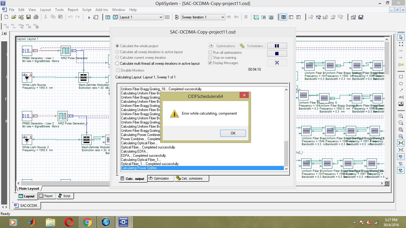
I installed version 14 from online.
And it gives me this error on calculating entire project.
What the hell .. how can version 14 be this screwed up!
Attachments:
Thanks a lot. Which version are u using bro? v 13?
The file does not open from version 14 for some weird reason.
I thought optisystems was backward compatible!
Okay thanks. Could u please tick the checkbox : “Show Eye Diagram”, and send me eye diagram for user 1 or user 2 please.
I needed the eye diagram actually more.
Or if u want, u can make user 3 work somehow in that osd file.
But if u use my coding as mentioned above, it should give the right result. I do not have access till tuesday.
Please help out.
User 1 FBG connection attached below.
Attachments:
I am entirely helpless and I have nobody to help me.
My work is due in a few days and I am already having panick attacks.
Brother, I will only get access to optisystems on tuesday.
I checked with others. For my project with 3 users, the algorithm that I wrote above is correct.
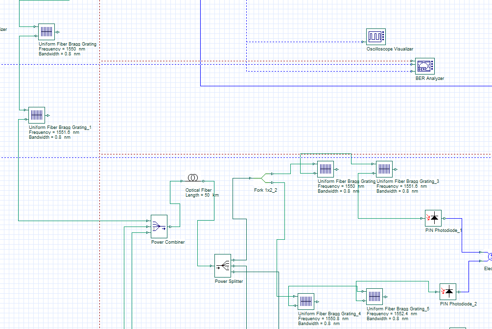
So for each user, I will have 2 FBGs at encoder side, and 4 FBGs at decoder side (for complementary detection/ 2 Top and 2 bottom FBG arrays). If possible, could you please be kind enough to just edit that osd file and instead use 2 FBGs for each user at encoder side, and 4 FBGs for each user at decoder side using the wavelength values that I mentioned? And white light source frequency should probably be the center frequency (1550.8 nm).
If it runs after this work, then my project will be successful. Its due in a few days and I have no access till tuesday.
Its just 5 minutes work for u.
Please be kind enough to help this little brother out.
Sample file? I got that file from the discussion link you shared, and it seemed to be Miss Kaurs completed thesis work.
Anyway, my project basically is for 3 users, sending 1010, 1100 and 1001. Can u check my encoding and decoding algorithm? I used complementary/balanced detection.
So we have 4 wavelength values –
lamda 1 = 1550 nm
lamda 2 = 1550.8 nm
lamda 3 = 1551.6 nm
lamda 4 = 1552.4 nm
Walsh code for Encoding :
User 1 (1010) : 2 FBGs at encoder coded with lamba 1 and lamda 3 (lamda 2,4 are cut off)
User 2 (1100) : 2 FBGs at encoder coded with lamba 1 and lamda 2
User 3 (1001) : 2 FBGs at encoder coded with lamba 1 and lamda 4
Walsh code for decoding using complementary/balanced detection :
User 1 (1010) : 2 top FBGs at decoder coded with lamba 1 and lamda 3, 2 bottom FBGs at decoder coded with lamba 2 and lamda 4
User 2 (1100) : 2 top FBGs at decoder coded with lamba 1 and lamda 2, 2 bottom FBGs at decoder coded with lamba 3 and lamda 4
User 3 (1001) : 2 top FBGs at decoder coded with lamba 1 and lamda 4, 2 bottom FBGs at decoder coded with lamba 2 and lamda 3
That sounds logical?