Optiwave software can be used in different industries and applications, including Fiber Optic Communication, Sensing, Pharma/Bio, Military & Satcom, Test & Measurement, Fundamental Research, Solar Panels, Components / Devices, etc..
OptiSystem is a comprehensive software design suite that enables users to plan, test, and simulate optical links in the transmission layer of modern optical networks.
OptiSPICE is the first circuit design software for analysis of integrated circuits including interactions of optical and electronic components. It allows for the design and simulation of opto-electronic circuits at the transistor level, from laser drivers to transimpedance amplifiers, optical interconnects and electronic equalizers.
OptiFDTD is a powerful, highly integrated, and user friendly CAD environment that enables the design and simulation of advanced passive and non-linear photonic components.
OptiBPM is a comprehensive CAD environment used for the design of complex optical waveguides. Perform guiding, coupling, switching, splitting, multiplexing, and demultiplexing of optical signals in photonic devices.
The optimal design of a given optical communication system depends directly on the choice of fiber parameters. OptiFiber uses numerical mode solvers and other models specialized to fibers for calculating dispersion, losses, birefringence, and PMD.
Emerging as a de facto standard over the last decade, OptiGrating has delivered powerful and user friendly design software for modeling integrated and fiber optic devices that incorporate optical gratings.
Yes. my Project is simulation of a sensor system. this sensor send an optical signal through a bidirectional coupler and a bidirectional fiber and then reflect it from bidirectional reflector. I have written a Matlab code to extract Phase of received signal.
and I also want to save received signal in stl format or any format,that I can.
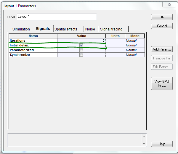
what does “Initial delay” exactly do and when must i enable this option?
Hi. my project need a lot of time for simulating. but I send for you a Simple Project that can show you my real Problem.
My problem is that i must enable “Initial delay” in “signal” tab of “Layout Parameters”.
if i enable “Initial delay”, i get error in “Save Spice Stimulus File”.
if i dont enable this option, data will be saved in stl format successfully but my output signal is not a valid output and also “MATLAB Component” will not run in Simulation.
I completely get confused!!!
I upload for you my simple project and a picture of “Initial delay” setting in my project.
Hi.
thank you for answering.
I want to save an electrical signal in my OptiSystem Project for further analyse ,in stl file format.
Now I understand my problem.
during simulation, from iteration 1 to 10 , this signal is Null(I connect an oscilloscope visualizer and see nothing! )
after iteration 11 oscilloscope visualizer shows that signal.
I guess my problem is because that Input signal of “Save Spice Stimulus File” cant be Null.
I think a trick to solve this problem!!!
I work with Optisystem 13.