Optiwave software can be used in different industries and applications, including Fiber Optic Communication, Sensing, Pharma/Bio, Military & Satcom, Test & Measurement, Fundamental Research, Solar Panels, Components / Devices, etc..
OptiSystem is a comprehensive software design suite that enables users to plan, test, and simulate optical links in the transmission layer of modern optical networks.
OptiSPICE is the first circuit design software for analysis of integrated circuits including interactions of optical and electronic components. It allows for the design and simulation of opto-electronic circuits at the transistor level, from laser drivers to transimpedance amplifiers, optical interconnects and electronic equalizers.
OptiFDTD is a powerful, highly integrated, and user friendly CAD environment that enables the design and simulation of advanced passive and non-linear photonic components.
OptiBPM is a comprehensive CAD environment used for the design of complex optical waveguides. Perform guiding, coupling, switching, splitting, multiplexing, and demultiplexing of optical signals in photonic devices.
OptiFiber The optimal design of a given optical communication system depends directly on the choice of fiber parameters. OptiFiber uses numerical mode solvers and other models specialized to fibers for calculating dispersion, losses, birefringence, and PMD.
Emerging as a de facto standard over the last decade, OptiGrating has delivered powerful and user friendly design software for modeling integrated and fiber optic devices that incorporate optical gratings.
OptiConverge is a collaborative integration framework that seamlessly combines two or more Optiwave products (e.g., OptiSystem, OptiSPICE, OptiFDTD, etc.) and other third party products into unified solutions. Designed to streamline complex workflows, it empowers users to achieve their goals faster by harnessing the collective power of our trusted Optiwave tools.
hello Cem,
thank you for your interested
actually in my design i can get the signal now in the downlink direction but i have a problem in the up link signal where i can not get clear signal
this is my design and i hope you will help me
thank you alot
hello Ranjeet,
the problem is very clear and its :
the RF spectrum analyzer and electrical carrier analyzer did not give the same value for signal power as the pic show.
Regards
hello Fayiqz,
thank you for your interested
actually i used electrical power meter and its result was more closer to the electrical carrier analyzer results
but the question is how can we get the same results and why this happened
thank you again for your helping
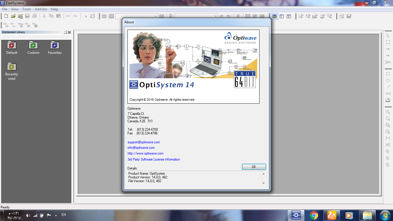
i installed it and it is run a 30-days trial optisystem 14 64-bit , and run well .
there is some additional component in , you can try to use it if you want without any risk.
Regards.
hello,
i am using optisystem 13 32-bit to design OFDM radio over fiber system that carried LTE signal over fiber optic channel and i am facing aproblem in getting a big BER value ( 0.33 ) and low Q factor but clear constellation diagram , even when run the simulation without any fiber channel (( only modulate and demodulate )) it still give me the same BER value without any change , i hope you to give me the reason why that happened and how can i get the right BER that depending to the channel .
thank you very much