
Base
| Full Name | K. Esakki Muthu |
| Organization | Anna University |
| Job Title | Research |
| Country |
Forum Replies Created
Thank you Scott.
Again I see different results on observation point and observation line. I am launching a a vertical input plane with 1 V amplitude at 1.55 um, when I use observation point , the result is exactly at 1.55 um, but when I use observation line I am getting at results at different wavelength. I have attached my results for your reference. Please have a look at it.
Thank you Scott. I will create my own threads for future queries, Thank you again.
Dear Scott,
I am designing a AND gate using 2D photonic Crystal . I don’t know how to get the output power spectrum, time response and calculate the data rate supported by the designed logic gate.
Please help me
Global bitrate should be same as the PRBS bitrate. Just Check it.
can you please show your circuit diagram? The frequency separation between the 193.07 and 193.13 THz is 60 GHz. thats why you are getting 60 GHz RF signal.
Io(t)= R |Eo(t).Eo(t)*|, Where R is the reponsivity , Eo(t) is the optical field and Eo(t)* is the complex conjugate of the field.
Dear Philip Weetman,
Let us discuss.
Thank you
Best Regards,
K.Esakki Muthu
Dear Philip Weetman,
The power reduction problem found in the earlier versions are rectified in the Optisystem 14. However, a new problem has emerged now, the power combiner in version 14 just simply combines two signal as it is but it is not responding to the phases of the input signal ( Version 12 and 13 does not have this problem). Kindly let me know how to solve this.
Thanks in advance
The power combiner works well in Optisystem version 14. But now it has become phase insensitive.
I gave -5,5,5,5 dBm input power at the 4 port combiner.. but the resultant is 8.078 dBm. why? any one please explain am using Optisystem 13
Thanks in advance
Please go through the attachment
Attachments:
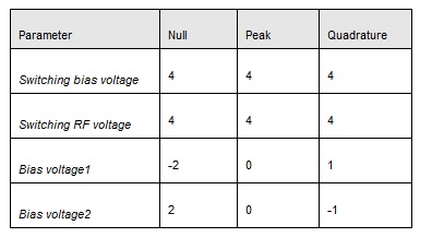
Mr. Fadil is referring to optical single sideband (SSB) modulation i think. It is very easy to generate SSB just controlling the biasing the MZM
Thank you
Good Idea, Thank you Alistu.
Dear Alistu,
I have tried this personally, if we keep Global bit rate and PRBS bit rate different, then the results are different.