Base
| Full Name | Ahmad Mahmood |
| Organization | National University of Science and Technology Pakistan Islamabad |
| Job Title | Student |
| Country |
Forum Replies Created
Thank you sir
Respected Sir, Abdullah Ismail,
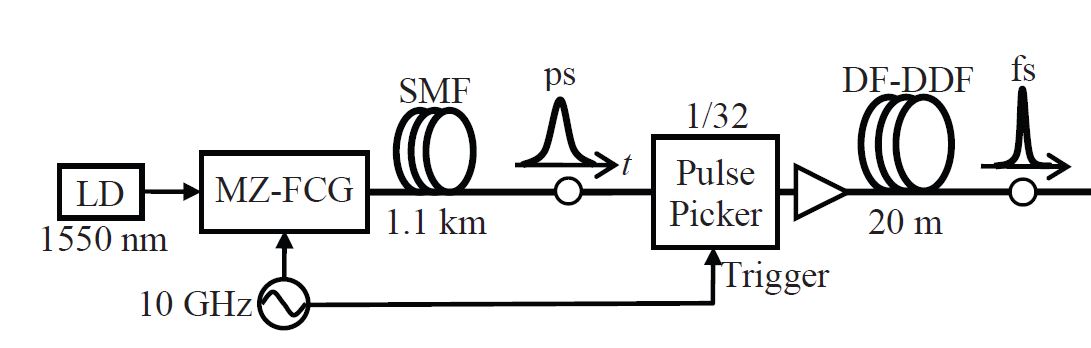
May you please guide me which component can I use in optisystem for pulse picker. Guide please.
Attachments:
Respected Sir,
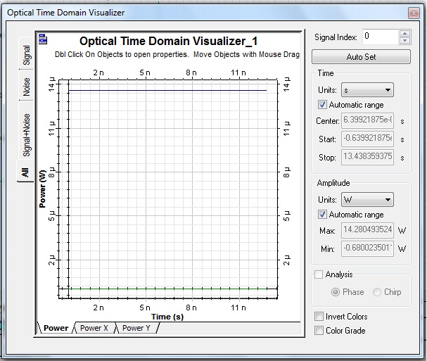
The circuit you provided is working very fine but the output of the WDM DeMux is not as the Wave is at the output of the modulator. Please Help in this regard. Thanks in anticipation.
Attachments:
A bundle of thanks for this help respected Sir.
A bundle of Thanks Sir. May you please refer me the paper related????
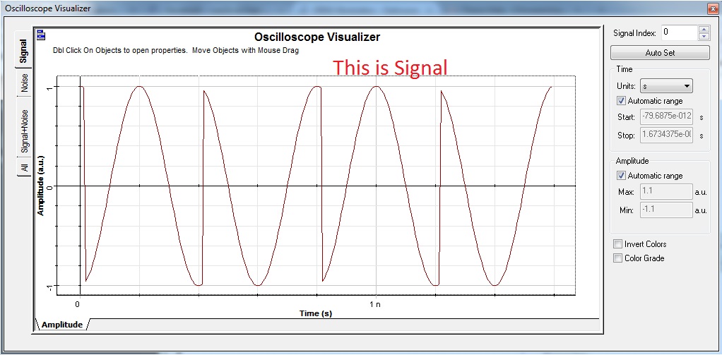
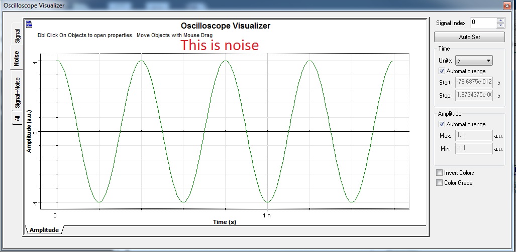
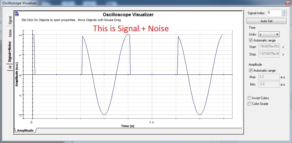
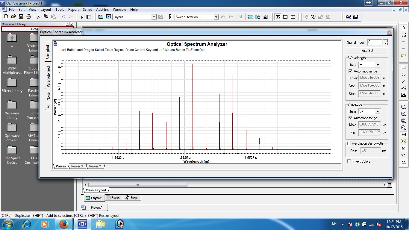
Here is the output of the project
Attachments:
Hi Sasha
you should just use a sequence of 0 instead of 00000000 on user defined sequence as the initializer should just send 1 bit at start to initialize the XNOR gate after that the delayed version of output will be sent at the input of XNOR see the file attached by Damian.
Yes I just changed BER analyzer not any parameter of it…… 
I just change the BER analyzer
Attachments:

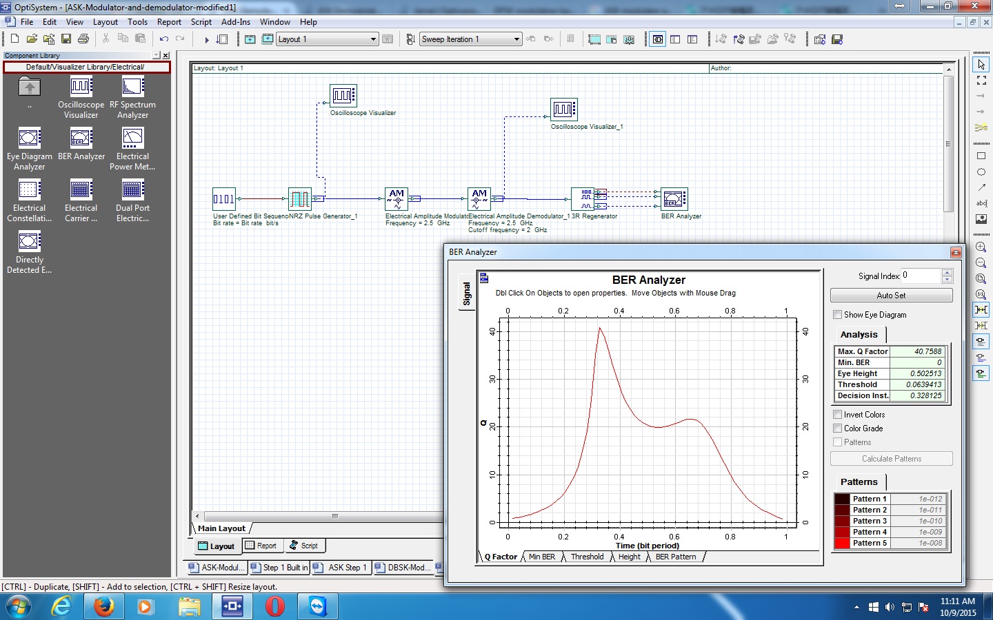
Also My supervisor says that we should not use 3R regenerator as it is very costly component. Here is snapshot of my BER in optisystem 13.
Attachments:
Alistu the your new circuit is also showing in optisystem 13 for me. See this.
Attachments:
The version 13 has some problems with BER analyzer but in version 7 its doing good Thanks again alistu
A bundle of thanks alistu You are more than a nice professor ………..
May God Help you in all walks of life always….. 
thanks alistu for your response I have used it but it does not give me NRZ pulse back to calculate the BER. it give some strange signal
Hi Sasha
the circuit you suggested is giving output after setting frequency parameters but there is a problem it gives the same amount of noise at the out put. More over you set the modulation constant of Phase Modulator to 1 degree so its not giving PSK signal to get BPSK we’ll have to set it 180 degree for QPSK 90 degree and for 8 PSK 45 degree. As we required BPSK we set it to 180 degree but now changed phase of output interfere with noise and give us the disrupted output. see the modified circuit and help if you can We want refine signal without noise.
Thanks in anticipation.