Optiwave software can be used in different industries and applications, including Fiber Optic Communication, Sensing, Pharma/Bio, Military & Satcom, Test & Measurement, Fundamental Research, Solar Panels, Components / Devices, etc..
OptiSystem is a comprehensive software design suite that enables users to plan, test, and simulate optical links in the transmission layer of modern optical networks.
OptiSPICE is the first circuit design software for analysis of integrated circuits including interactions of optical and electronic components. It allows for the design and simulation of opto-electronic circuits at the transistor level, from laser drivers to transimpedance amplifiers, optical interconnects and electronic equalizers.
OptiFDTD is a powerful, highly integrated, and user friendly CAD environment that enables the design and simulation of advanced passive and non-linear photonic components.
OptiBPM is a comprehensive CAD environment used for the design of complex optical waveguides. Perform guiding, coupling, switching, splitting, multiplexing, and demultiplexing of optical signals in photonic devices.
The optimal design of a given optical communication system depends directly on the choice of fiber parameters. OptiFiber uses numerical mode solvers and other models specialized to fibers for calculating dispersion, losses, birefringence, and PMD.
Emerging as a de facto standard over the last decade, OptiGrating has delivered powerful and user friendly design software for modeling integrated and fiber optic devices that incorporate optical gratings.
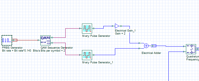
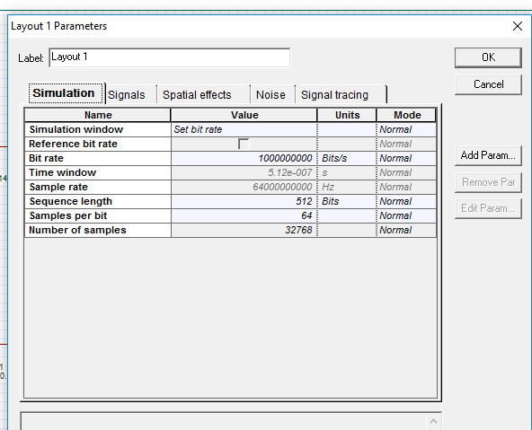
I have lessen the time of samples by dividing so that for whole time array the total duration remain 512ns, is this correct? input time array size is 32768 samples length, and outputport1 time array size is 320256.
see attachment.. kindly help as no example is given in which input and put ports have different structures.
Jawad.
you can change sample rate even without changing the data rate. just multiply sample rate with 0.1/0.2 or 2,4etc whatever rate you want by changing normal to script mode.
But remember, it sometimes changes the frequency of sinusoidal components. so try it.
Thank you Damian , I think excellent answer. But That’s the problem, that in a sequence manner, each matlab component will overwrite the outputPort of previous one. So you mean for each matlab component simulation I have to pause the simulation. It will become complex if I use more matlab components. Is not there any other option?
Thank you Ahmad Atieh for listening to the query.
I think there is issue in PRBS and global bit rate. As whenever I want to get such type bit rate from PRBS , CIDF scheduler error comes. Kindly find the attached layout.
I have understood your problem. I am working on the same problem, but unfortunately I am still stuck in the issue. I have not found any compatible code for Optisystem. You would have to find A/D code for matlab and then make changes in that code. I hope some senior member help us here.
The same problem here. you should use matlab component to transfer your analog rf signal to matlab. code in matlab for A/D and then transfer again your digital signal to signal to optisystem for further operation.
Thank you Damian Marek.
Actually I am using Matlab component and transferring my analog RF signal to matlab for digitizing there. But the problem here is how can I import analog signal from optisystem? Should I use SignalTransfered=InputPort1.Sampled.Signal for transferring RF signal from optisystem into matlab?
My second point is, the InputPort1Sampled.Signal structure stores values in array, are these the amplitudes of RF signal at sampled times?
Kindly help.