Optiwave software can be used in different industries and applications, including Fiber Optic Communication, Sensing, Pharma/Bio, Military & Satcom, Test & Measurement, Fundamental Research, Solar Panels, Components / Devices, etc..
OptiSystem is a comprehensive software design suite that enables users to plan, test, and simulate optical links in the transmission layer of modern optical networks.
OptiSPICE is the first circuit design software for analysis of integrated circuits including interactions of optical and electronic components. It allows for the design and simulation of opto-electronic circuits at the transistor level, from laser drivers to transimpedance amplifiers, optical interconnects and electronic equalizers.
OptiFDTD is a powerful, highly integrated, and user friendly CAD environment that enables the design and simulation of advanced passive and non-linear photonic components.
OptiBPM is a comprehensive CAD environment used for the design of complex optical waveguides. Perform guiding, coupling, switching, splitting, multiplexing, and demultiplexing of optical signals in photonic devices.
OptiFiber The optimal design of a given optical communication system depends directly on the choice of fiber parameters. OptiFiber uses numerical mode solvers and other models specialized to fibers for calculating dispersion, losses, birefringence, and PMD.
Emerging as a de facto standard over the last decade, OptiGrating has delivered powerful and user friendly design software for modeling integrated and fiber optic devices that incorporate optical gratings.
OptiConverge is a collaborative integration framework that seamlessly combines two or more Optiwave products (e.g., OptiSystem, OptiSPICE, OptiFDTD, etc.) and other third party products into unified solutions. Designed to streamline complex workflows, it empowers users to achieve their goals faster by harnessing the collective power of our trusted Optiwave tools.
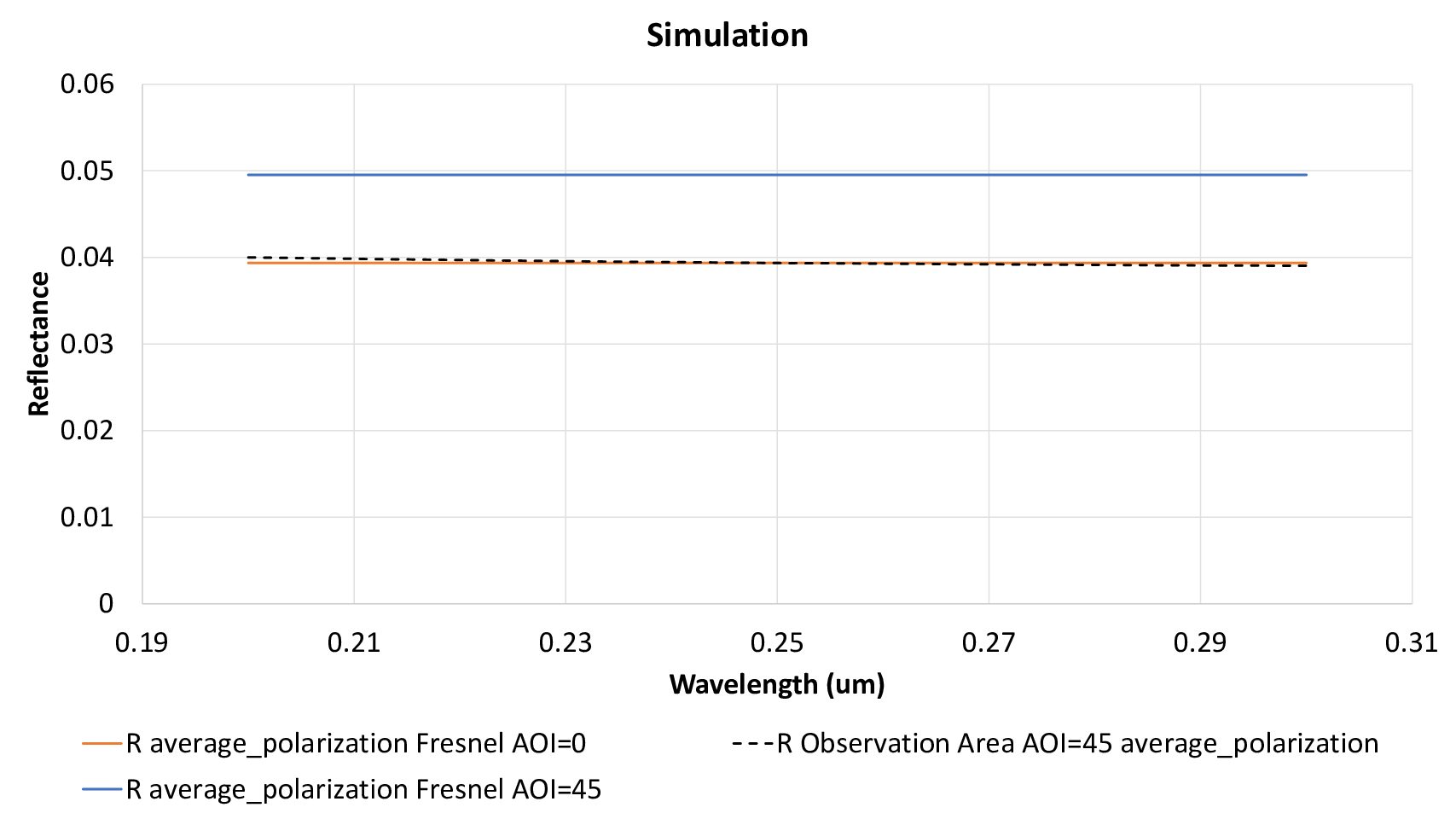
And this is the result of the simulation using a tilted wave at 45degrees compared with what you obtain using Fresnel equations. All reflectances are averaged for both polarizations.
Thanks for your feedback! I am using the 32-bits free version.
Regarding your answer, the point is that the nano structures are smaller than the wavelength, so there should not be any divergence or convergence. Indeed, looking at Ez in the reflected field, I see that is close to 0 across the spectrum, meaning that there is not diffraction due to the nano structures.
I tried to move both observation area and observation points further to meet the far field approximation and still results are very different at the target wavelength. I am clueless 🙂
Some additional information: I have attached the design file, and in the attached picture you can see the differences between the reflectivity calculated from an observation area and from an observation point. I am only interested on specular reflectivity
Regarding R from the observation area, I used the power spectrum option and then I calculated Pz normalized to input plane.
Regarding R from the observation point, I calculated the normalized DFT for Ex, Ey, and Ez and then R=(Ex)^2+(Ey)^2+(Ez)^2
Overall the coincidence is acceptable, but the ball should enhance the reflectivity at 0.0165 microns, and it only happens when I calculate R from the observation point. However, when I use the observation area, results are different.