
Base
| Full Name | ali |
| Organization | wsi |
| Job Title | student |
| Country |
Forum Replies Created
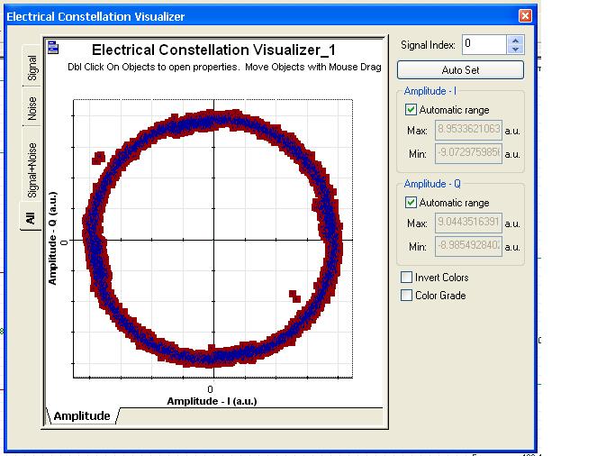
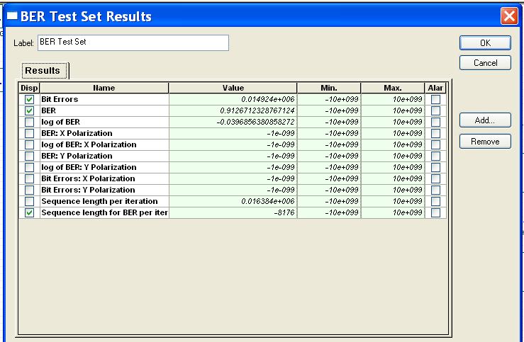
i attach constellation+BER result
Attachments:
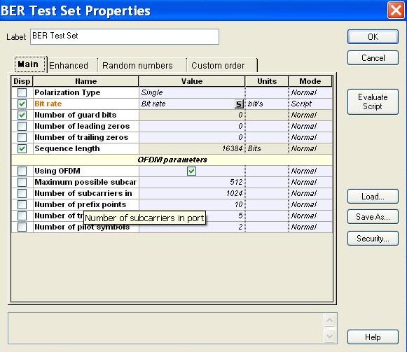
i said,”in section ofdm mod. no appear item pilot symbols ” I mean, change the parameters IN ofdm modulator
but appear pilot symbols in section BER test set
if possible Changes you saying apply in sent my file?
i use optisystem 13.
in section ofdm mod. no appear item pilot symbols .
if possible Please help clear
thanks
i do not have key but do if format hard Problem solved
hi
You will have no problem using version 13
Version 13 to use
in section “BER TEST set properties\ofdm parameters\pilot symbols” i do change pilot symbols and change other parameters in the section but no better result.
hi alitsu
To resolve the problem with the length of the fiber, and even more, what should I do?
hi
Why file attached with high O.S.N.R but is bad performance? What are the defect?
Attachments:
hi alitsu
some questions
1- bit rate is set in two places, one in the global parameters and other in the PRBS GEN
What’s the difference?
is have a relationship with toghter?
Because if change bit rate in global parameters result BER is different
2-One advantage of ofdm set cyclic prefix for avoid isi
Where should determine this parameter?i change in ofdm mod. but i did not see change in the BER
3-where i do download optisystem 13.0.3 ? because i have v. 13.0.2
Very good’ve described.
Thank you
hi alitsu
you said:The reason for the BER=1 in one of the channels is the symbol rotation problem
But the constellation diagram does not show large spin.
The number 110 seems a little difficult to guess.
You can give me a little guide?
Hi alistu
No, I mean, you said it was not
I mean, the question was why the symbol (1) in the third quarter numbers did you?
Do you come from experimentation to -145 number? Or did the calculations?
thanks
hello alistu
How did Marking symbol?
Why did you symbol into these numbers?
thank you alistu
Is simulation file in this case that would help me do you know?