
Base
| Full Name | Abhilash Achanta |
| Organization | Sri Sathya Sai Institute of Higher Learning |
| Job Title | Student |
| Country |
Forum Replies Created
No. Not at all acceptable. BER of 0.06 means there are 6 errors for every 100 bits of data. This cannot be corrected using FEC.
So, try reducing the fiber length until you get BER of 10e-3 which is acceptable
Did check the graphs in OFDM demodulation component?
There is no standard values for BER as such. It depends on the components on the link such as Laser, fiber’s attenuation, amplifiers and photodetectors. For whatever length you simulate, you MUST ensure that BER is below 10e-3.
When I ran my simulation for OFDM based 16-QAM link at 20 Km length, the BER value was zero.
Hi Jayeshkumar,
I am also working on RoF link. However, I am not considering WDM in my work and my range is upto 70 Km
Acceptable BER for RoF links is upto 10e-3. This value is known as ‘FEC limit BER’. This means that the we can tolerate any BER less than 10e-3 and the Forward Error Correction Codes (FEC) help in bringing down the BER to less than 10e-9.
I suggest that you run your simulation for different fiber lengths and check at what length BER is attaining 10e-3. This is the maximum distance your link can have.
I had attended an IEEE conference recently and one of them presented their work – BER comparison in ROF links.
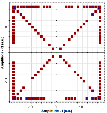
I don’t think the constellation diagram that you are seeing is due to noise. This is because the constellation looks orderly.
Did you try checking the constellation in OFDM demodulation component in project browser ?
If you are still facing same problem. Please send the simulation file so that I can take a look at it.
Hi,
Even I am simulating OFDM along with different modulation schemes.
There are two things that you can do:
1. Go to Project browser->OFDM demodulation component->Graphs->Contellation diagram
OR
2. How many subcarriers(S) and total carriers(T) are you using?
Go to the properties of constellation diagram visualizer and replace bitrate with bitrate*S/T.
Damian,
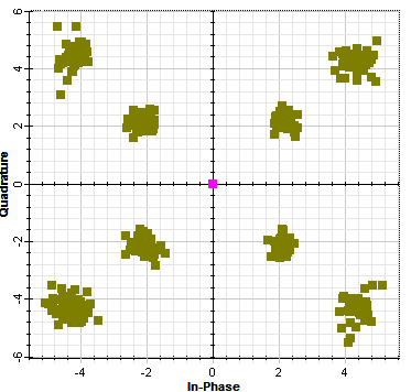
I checked the graphs that are generated in OFDM demodulation component and they resemble 8-QAM scheme (I saw one of your post which says this, Thanks!)
Please find the constellation diagram attached
Attachments:
Hi Adnan,
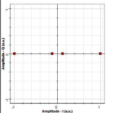
The constellation diagrams at the transmitter end are okay now.
At the receiver end, BPSK and 8-QAM are not as expected.
Please find screen shots and simulation file attached.
Thanks for the help.
Hi burhan and aabid,
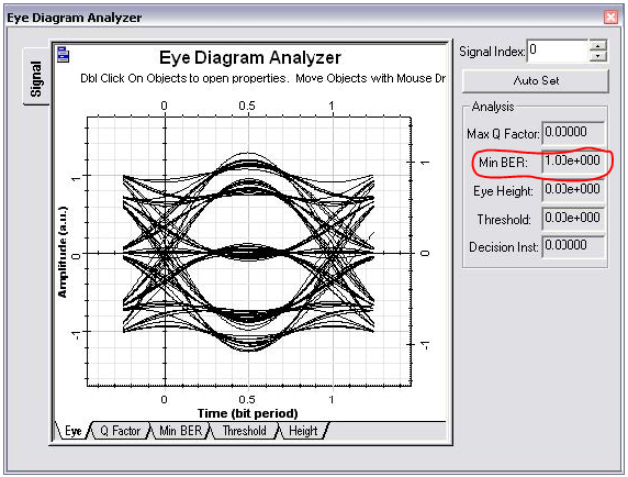
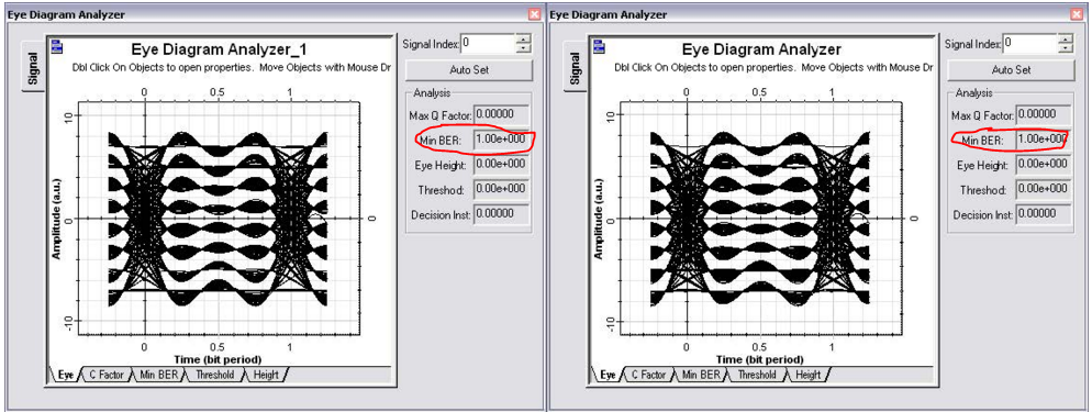
I’m just thinking how a OptiSytem sample file could give 100% error.
Sample files are supposed to give results close to practical values right?
I have even observed in the tutorials section for QAM and DPSK.
The min BER is 1 which means there are 100 % errors in received bits?
Attachments:
Hi Karan,
The Laser’s rise time is the time required for laser output from 10% to 90% of total power.
Rise time is a factor that decides the 3db Bandwidth of the Laser. ( risetime = 0.35/BW )
So, for rise time = 35 ps. The BW = 1 Gbps.
In the layout attached, I directly modulated the Laser above 1Gbps and the output of laser showed absolutely no distortion.
I tried this with the analog signals also, but the result is the same.