Before having the FDTD component and any simple possibility to use a multidirectional optical component based on a modified S-data approach, we have to analyze some structures suitable for the FDTD like the ring resonator by the means already available.
Figure 22: Ring resonator as the OptiBPM layout
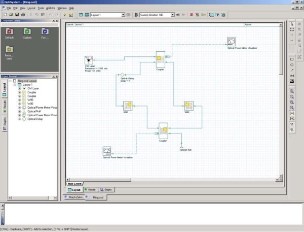
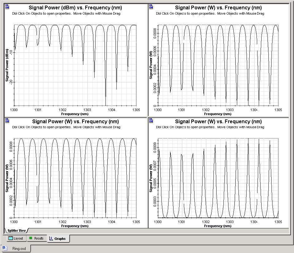
The solution for the fourth example is obvious. We will demonstrate the solution on the simplest level. The circuit must be divided at least into four elements (see Figure 23). Namely, we can see the two coupling regions and several bent elements. They are symmetrical, so we can simulate just one using BPM. We also have to describe the phase delay (perhaps also losses) in the bent arcs. The realistic ring resonator design and its representation in OptiSystem is shown in Figure 23 followed by the wavelength dependent responses.
Figure 23: Ring resonator system schematic
Note that this circuit has a fundamental difference to the previous ones. In the simulation, one of the outputs goes in a circle and is eventually connected to an input. Strictly speaking this should forbid the calculation, since not all the inputs are known at the beginning of calculation. OptiSystem can accommodate this situation by including the delay element, an instruction that a solution should be found by iteration. In the first pass, the input is assumed zero, and the calculation proceeds until the output is transmitted to the first input. In a second pass, this input value from the previous iteration is used. In many cases, this iterative procedure converges to the steady state solution.
Figure 24: Wavelength dependencies of the ring resonator


