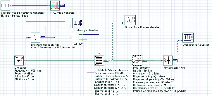
Polarization mode dispersion (PMD) can cause serious problems in high bit-rate transmissions. In this lesson, the PMD emulator component is used to demonstrate the distortions in the transmitted signal, caused by first and second order PMD effects. The system showed in Figure 1 is utilized in the simulations.
Figure 1: PMD system layout
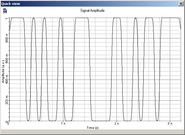
The system simulates the transmission of a sequence of pulses for a 10 Gb/s bit rate in a high PMD fiber with differential group delay of 71 ps, depolarization rate of 10.8°/GHz, and polarization chromatic dispersion of 1.3ps/GHz. In the simulations, attenuation and dispersion are set to zero. The input signal is a sequence of NRZ pulses showed in Figure 2.
Figure 2: Input sequence of pulses
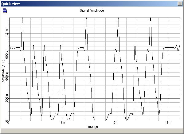
Simulations are carried out for two different polarizations of the optical input signal. Figure 3(a) shows the output signal for an input state of polarization (SOP) aligned with one of the two principal states of polarization, azimuth = 0 and ellipticity = 0. In Figure 3(b), the output signal is the same, but the input SOP is aligned with the other axis, azimuth = 90 and ellipticity = 0.
Figure 3: (a) Simulation results for input signals with azimuth = 0,
ellipticity = 0
Figure 3: (b) Simulation results for input signals with azimuth = 90, ellipticity = 0
In both cases, the main second order effect is due to the depolarization rate coefficient, since the polarization chromatic dispersion is too small to create a substantial deformation of the output signal.
The presence of power over-shoots on the sequences of “1”s, and the presence of energy on the “0”s are due to the imperfect cancellation of the pulses coupled on the orthogonal axis. The results found in the simulations are in agreement with the results presented in [1].
References:
[1]Cristian Francia, Frank Bruyere, Denis Penninckx, and Michel Chbat. ” PMD Second-Order Effects on Pulse Propagation in Single-Model Optical Fibers”. IEEE Photonics Technology Letters, December 1998.
[2]L. E. Nelson, R. M. Jopson, H. Kogelnik, and G. J. Foschini. “Measurement of Depolarization and Scaling Associated with Second Order Polarization Mode Dispersion in Optical Fibers”. IEEE Photonics Technology Letters, December 1999.


