The purpose of this lesson is to give an idea about the effects associated with cross-phase modulation (XPM) and four-wave mixing (FWM) accompanying the propagation of optical signals at different carrier frequencies in a nonlinear dispersive fiber [1].
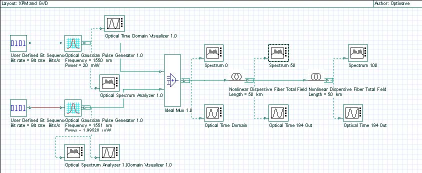
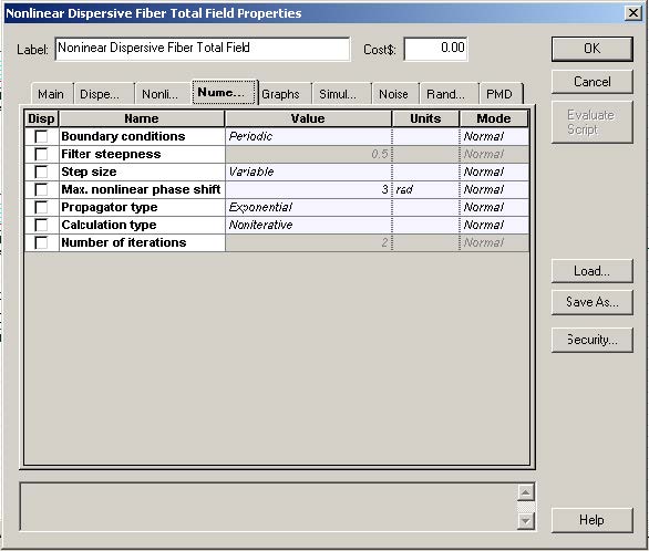
At first, we create the layout shown in Figure 1. The Numeric tab of the Nonlinear Dispersive Fiber Total Field component is shown in Figure 2. Note that the step size is much smaller compared to that used to simulate soliton propagation (see “Interactions of optical solitons”). Although the power levels here are far below the soliton regime, the bandwidth occupied by the signal is larger, and a small enough step-size is necessary to calculate the four-wave mixing products resulting from the interaction of the input signals accurately (see [2]). In this case the step-size is determined by the coherence length of the FWM process rather, than by the nonlinear length (associated with the self-phase modulation process).
Figure 1: Project layout
Figure 2: Nonlinear Dispersive Fiber Total Field Properties dialog box—Numeric tab
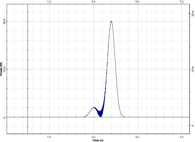
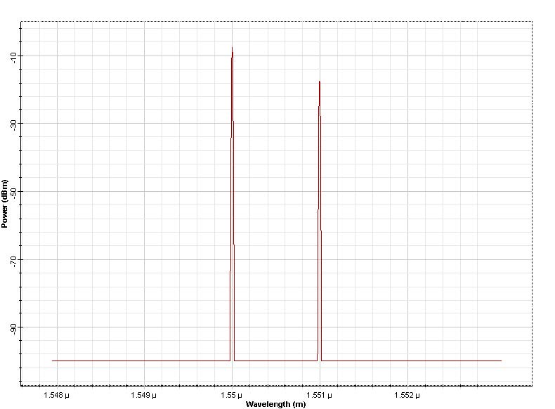
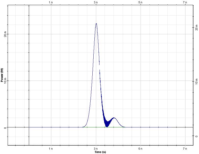
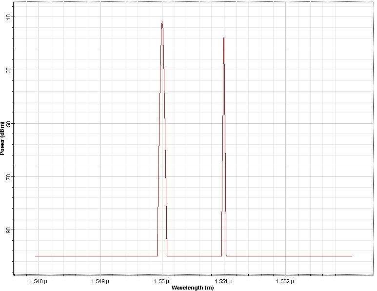
The input consists of two Gaussian pulses 800ps spaced in time and 1nm in frequency Figure 3. The fiber dispersion is D = 16ps/nm/(km). Note that the bandwidth we simulate is bigger than three times that of the input signal. This is done to avoid the any aliasing of the FWM products generated by the nonlinear interaction of the two pulses.
Figure 3: Input pulses and their spectrum
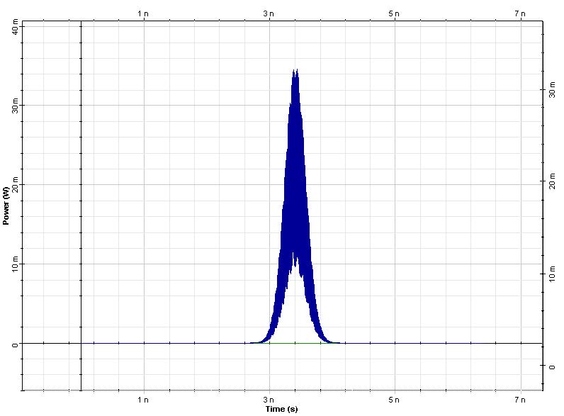
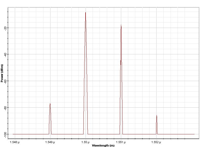
Figure 4: Pulses and their spectrum after of propagation in a lossless fiber 50 km
Figure 5: Pulses and spectrum after 100km of propagation
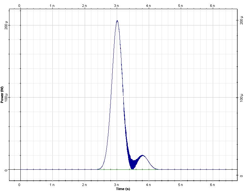
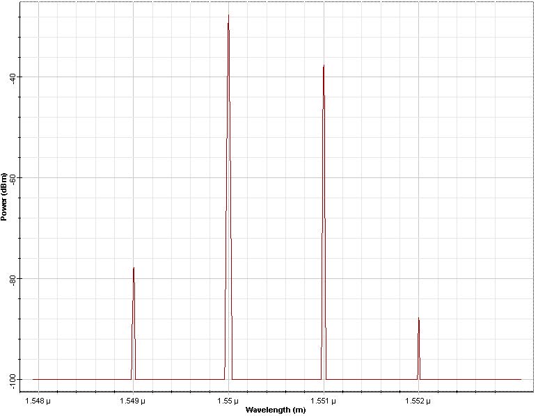
The pulse at 1551nm has 2 mW peak power so that SPM is negligible for this pulse at 100km fiber length. The pulse at 1550nm has 20mW of peak power and the effects of SPM are important for this pulse; the XPM on the 1551 nm pulse will be large. After 50 km propagation, the two pulses overlap and the spectrum of the pulse at 1551 nm is broadened (Figure 2 and Figure 3). This broadening is caused by the effect of XPM. It is interesting to note that the spectral broadening of the pulse at 1550 is larger. For this pulse the broadening is caused by SPM. On the other hand the broadening for the 1551 nm pulse (caused by XPM) is smaller due to the presence of GVD. The edge of the stronger pulse moves through the weaker pulse, the overlap time is diminished and so is the spectral broadening. At 50 km the four-wave mixing products (“spurious frequencies”, [2] at 1549 nm and 1551 nm) are evident. Now the bandwidth of the signal is three times that of the input signal. If the simulated bandwidth was insufficient to accommodate both the signal and the spurious frequencies the power of the FWM products would have been falsely translated into the bandwidth of the signal (aliased).
Figure 6: Figure 4 but including fiber losses
At 100 km, when the pulses are no longer overlapped and the FWM product have disappeared. The XPM induced spectral broadening for the pulse at 1551 nm has also vanished. This is because the effects accompanying the increase of the pulse overlap are opposite to those associated with the pulse separation (see [2]). The portion of the interfering pulse with falling intensity produces a frequency shift of the opposite sign to that previously produced by the rising edge [1]. This example illustrates that dispersion can result in a lessening of the effects of XPM and FWM in a lossless fiber. In a fiber with losses, the symmetry responsible for the disappearing of the spurious waves is no longer present—when the pulses start to overlap they contain more energy then when they start to separate—(as seen in Figure 6), and the spurious waves do not disappear.
References:
[1]F. Forghieri, R. W. Tkach, and A. R. Chraplyvy in: Optical Fiber Telecommunications vol. IIIa ed. I. Kaminow and T. Koch, chapter “Fiber Nonlinearities and their impact on Transmission Systems”.
[2]D. Marcuse, A. R. Chraplyvy, and R. W. Tkach, Journ. Lightwave Technol, 9, 121 (1991).


