The purpose of this lesson is to demonstrate the asymmetric spectral broadening caused by XPM.
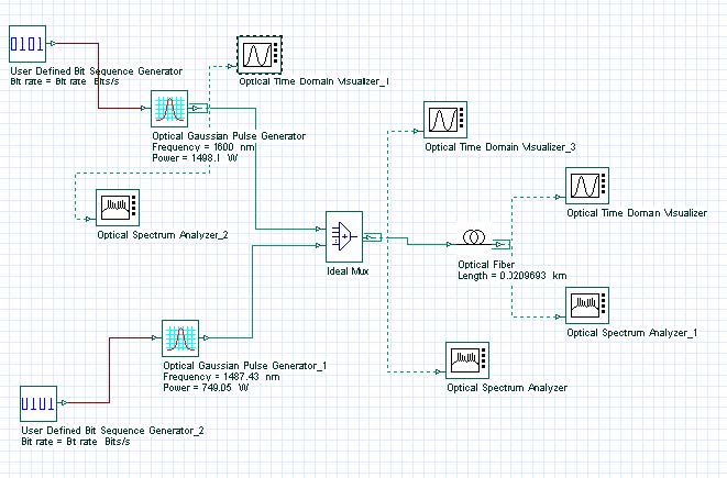
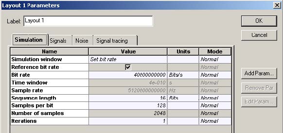
The layout along with the global parameters are shown in Figure 1.
Figure 1: Layout and global parameters
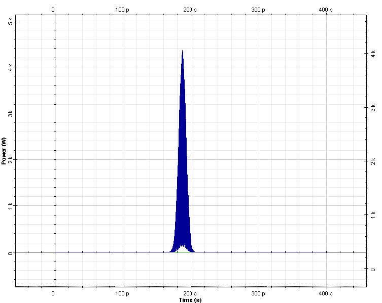
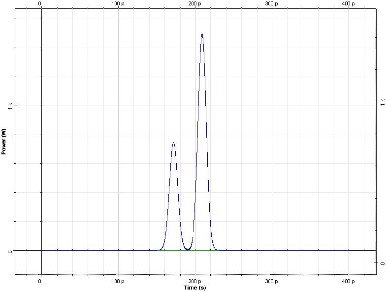
The input consists of two superimposed Gaussian pulses [1] (Figure 2).
Figure 2: Superimposed Gaussian pulses
The carrier wavelengths of the pulses are λ1 = 1487.4nm and λ2 = 1600nm ,
and the corresponding peak powers are P1 = 749.05W and P2 = 1498.1W .
Pulse duration (FWHM) is 0.5 bit (12.5ps). The fiber group delay, effective area are
relevant to those of SMF-28 and are specified as “wavelength dependent”.
The nonlinear refractive index value is n2 = 2.6 x 10⁻²⁰m2 / W . Constant step size
(50 mrad) is used. The effects of GVD are not taken into account. The output (after
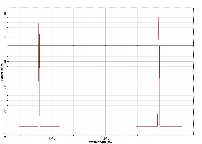
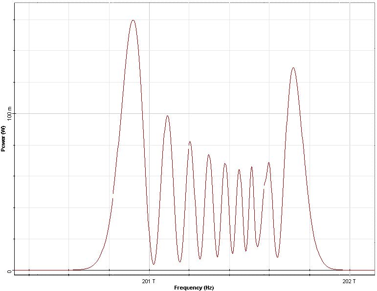
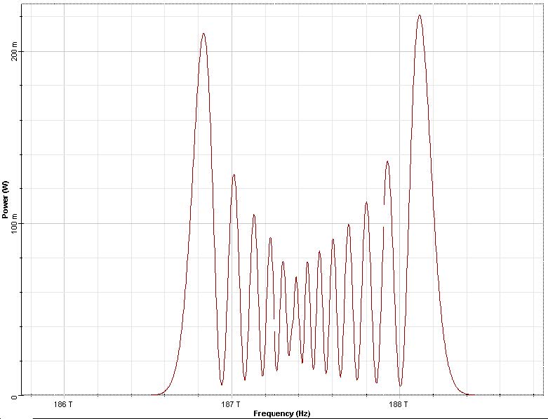
20.9m, corresponding to five walk-off lengths) is shown in Figure 3.
Figure 3: Output
The spectral asymmetry is caused by XPM. For the Pulse “1” (at 1487.4 nm) the asymmetry is more pronounced because the XPM is stronger for this pulse (P22P1=). Since the XPM induced spectral broadening depends on the sign of group velocity mismatch, the spectra presented in [1] are “mirror” images of those presented in Figure 3 since the latter are obtained in the anomalous GVD region (infrared) while those presented in [1] correspond to the visible region (normal GVD).
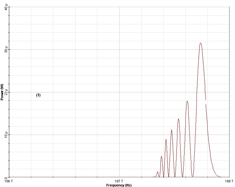
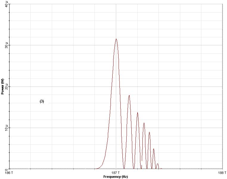
Figure 4: Output probe spectra
The time delays between the faster (pump) pulse and the slower (probe) pulse are equal to 0 ps (1), 15.014 (2) ps and 30.028 (3) ps.
Figure 4 demonstrates the spectral broadening, caused by XPM, induced by a strong “pump” pulse on a weak probe. To achieve this effect, the following changes are applied to the design layout.
The peak of the faster, (pump) pulse at λ1 = 1487.4nm is set to 1872.63 W. The
fiber length is made equal to four walk-off lengths, or, 16.77 m. The power of the probe
pulse (at 1600 nm) is set to a value much smaller than that of the pump pulse (0.06W).
Figure 4 shows the output probe spectra for three different value of the initial time
delay between the probe and the pump. The faster (pump) pulse is delayed with
respect to the slower (probe) pulse. There is a good agreement between the results
presented in Figure 4 and [1].
References:
[1]G. P. Agrawal Nonlinear Fiber Optics, 3rd edition, (2001) Chapter 7.


